
Solid Oxide Fuel Cells (SOFC) and (SOEC)
Contact: Dr.-Ing. Heike Störmer
SOFC
In the context of the turnaround in energy policy, research focusses on technologies that can be used for the decentralized production of renewable (green) hydrogen (electrolyzer) or the reconversion of hydrogen into electricity (fuel cell). Due to the high efficiency (> 80 % for cogeneration) and the good scalability (system sizes in the kW to MW range), systems based on the solid oxide cell (SOC) will be the key technology for achieving the climate targets.
SOCs contain a dense oxygen-ion conducting ceramic as electrolyte. The electrolyte is embedded between a porous electrode layer composed of a ceramic-metal composite at the fuel side of the cell and a nanoporous oxygen ion and electronic conducting ceramic layer at the air electrode of the cell. SOCs operate at temperatures above 550 °C. Figure 1 and 2 show the two different modes of SOC operation. Depending on the operation mode, the cells produce H2O and electricity consuming hydrogen (or natural gas) and oxygen (fuel cell mode, cf. Figure 1) or vice versa (electrolysis mode, cf. Figure 2).
In a fuel cell the chemical redox reaction of any fuel (hydrogen, natural gas) with air is separated into two partial reactions by a gas-tight, O2--conducting electrolyte as depicted in Figure 1. The dissociation of oxygen molecules and the reduction of oxygen atoms take place in the porous air electrode (cathode) while the fuel is oxidized in the porous fuel electrode (anode). Due to a gradient in oxygen partial pressure, oxygen ions propagate through the O2--conducting electrolyte ceramic from the cathode to the anode. The difference in chemical potentials between the cathode and anode results in a cell voltage in the order of 1 V. To realize a useful power output, the relatively small single cells are connected in parallel and in series using ceramic or metallic interconnects.
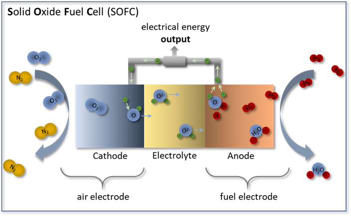
Figure 1: Functional principle of a solid oxide fuel cell (SOFC) in operation mode with hydrogen (H2) as fuel gas and oxygen (O2) as oxidant. At the air electrode, O2 is reduced to O2- and migrates through the electrolyte to the fuel gas electrode. The oxidation of H2 at the fuel electrode releases electrons and produces water (H2O).
In contrast to the fuel cell, an electrolysis cell works in reverse (see Figure 2), producing hydrogen from steam by electrolysis. Operated at temperatures above 700 °C, a high efficiency is achieved because the energy required for the electrolysis process is reduced that less electrical energy is needed to initiate the endothermic splitting of the water molecules. The need for thermal energy is covered by the heat loss that occurs in the cell, so that efficiencies of more than 80% can already be achieved today.
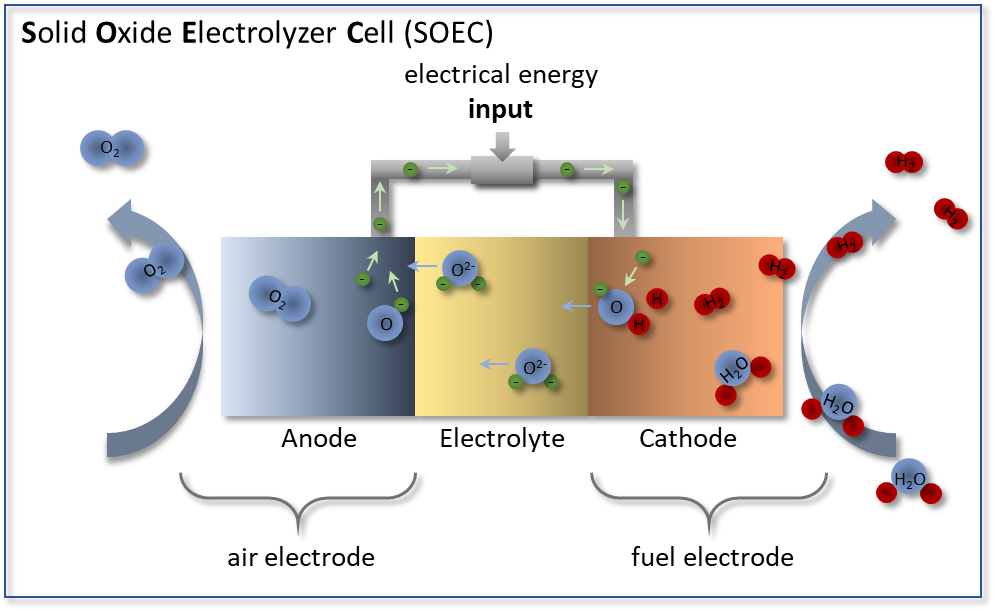
Figure 2: Functional principle of a solid oxide electrolyzer cell (SOEC) in which steam (H2O) is introduced at the fuel electrode. At the fuel electrode, H2O is reduced to hydrogen H2 by adding electrons. The resulting oxygen ions O2- migrate through the electrolyte to the air electrode where they oxidize to oxygen O2.
The decisive factors for SOC systems are the efficiency of single cells and the lifetime of the components. The research at LEM in the field of SOC materials focuses on both, the chemical and microstructural characterization of new materials as well as investigation of degradation processes of commonly used materials.
SOFC-project WirLebenSOFC: Comprehensive analyses of the SOFC are being carried out in the visionary project WirLebenSOFC (Verständnis der Wirkzusammenhänge der Alterungsmechanismen zur Lebensdauervorhersage von SOFCs, Understanding the Interactions of Aging Mechanisms for Lifetime Prediction of SOFCs) which is funded by the German Federal Ministry of Education and Research (BMBF). A broad consortium of project partners from industry (Robert Bosch GmbH, RJL Micro & Analytic GmbH) and science (Karlsruhe Institute of Technology, Karlsruhe University of Applied Sciences, Research Center Jülich, Aalen University of Applied Sciences) is applying a wide range of experimental methods (microstructure analysis, electrochemical characterization) and simulative techniques (including the use of machine learning algorithms) to investigate the degradation mechanisms and predict the lifetime.
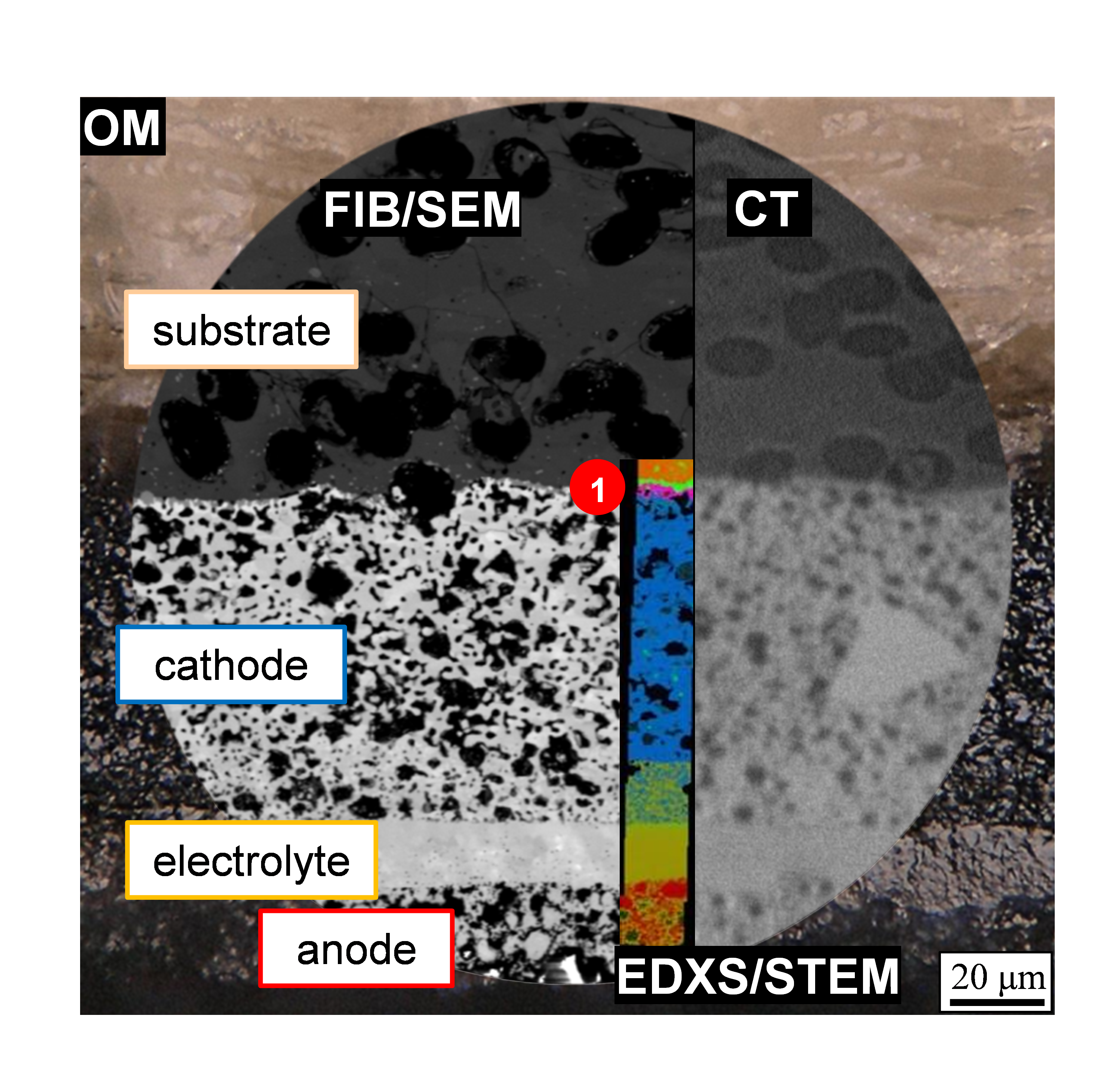
Figure 3: Use of various multi-scale analytical methods to study the SOFC: optical microscopy (OM), focused ion beam and scanning electron microscopy (FIB/SEM), X-ray computed tomography (CT) and energy-dispersive X-ray spectroscopy in the scanning transmission electron microscope (EDXS/STEM). By combining the investigation techniques, the information output can be maximized. Image data from previous project KerSOLife100.
High temperatures during manufacturing and operation (operation at over 550 °C, manufacturing at over 1000 °C) as well as oxidizing and reducing atmospheres are a major challenge for the components used in the SOFC. In the project, a microstructural characterization of the components is performed in the scanning electron microscope and scanning transmission electron microscope. This includes a three-dimensional microstructural analysis of the electrode structure as well as a high-resolution investigation of the secondary phases formed during manufacture and after operation. Figure 3 shows the differences in image information content that can be achieved with the imaging techniques used. Figure 4 clearly illustrates that for the foreign phases Sr2La8(SiO4)6O2 and ZnMn2O4 detected at position (1) in Figure 3, a performance-reducing influence due to inhibited oxygen transport paths can be excluded. Conclusions regarding the microstructure of the SOFC are derived from the investigations carried out, which can be used in collaboration with project partners to describe aging mechanisms and make lifetime predictions.
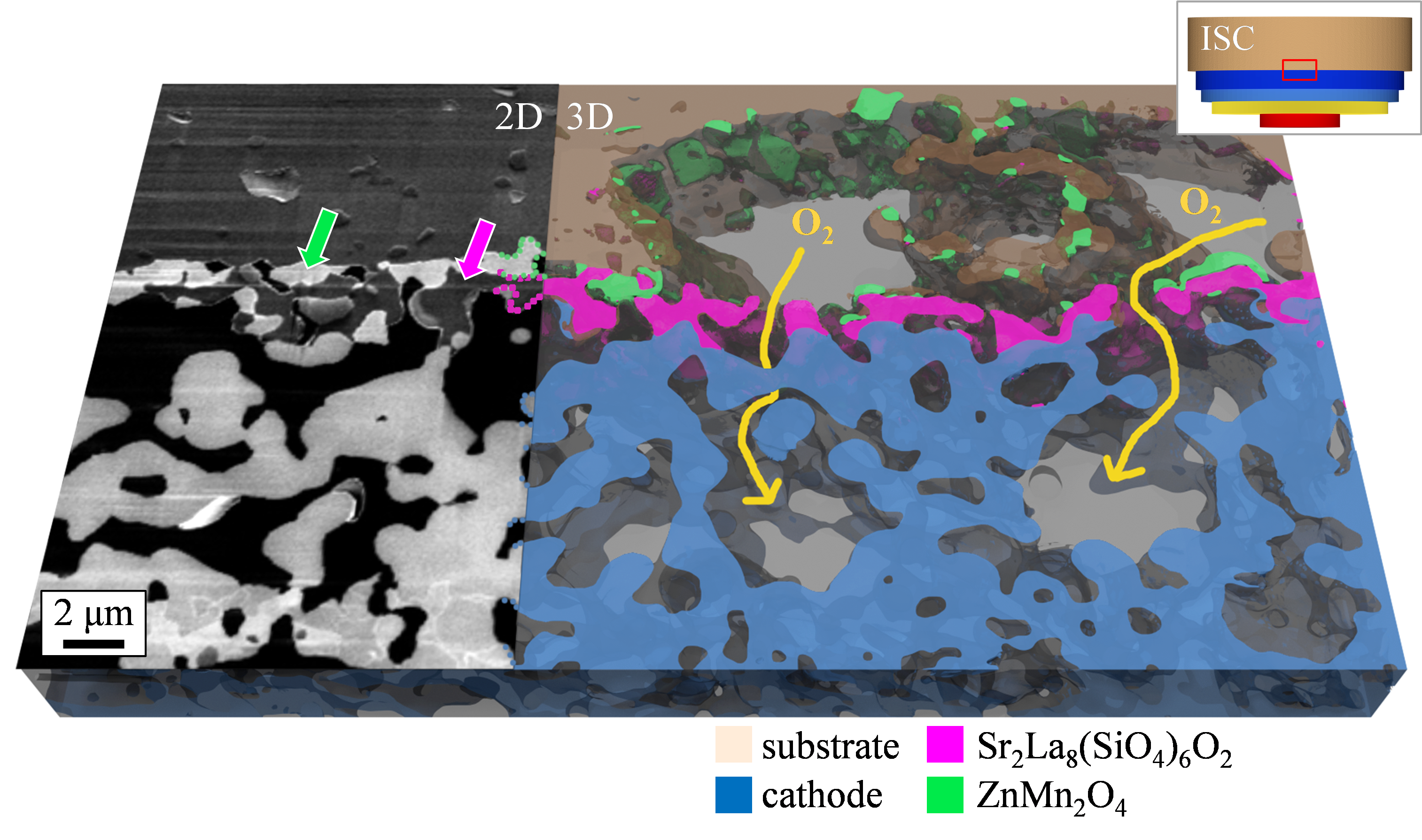
Figure 4: Interface between substrate and cathode: as the secondary phases do not block the oxygen transport there is no negative influence on cell performance. Image data from previous project KerSOLife100.
SOEC
SOEC project H2Giga: In the H2Giga lead project, the series production of electrolyzers is to be supported in order to cover the future demand for hydrogen. For this purpose, efficient electrolyzers must be developed that are durable, robust, cheap to purchase and scalable for industrial purposes. Within the project, different electrolysis technologies are being developed. These include PEM electrolysis (proton-conducting membrane), alkaline electrolysis and high-temperature electrolysis.
The Laboratory for Electron Microscopy (LEM) is working in the "HTEL - Ready for Gigawatt" network with the Institute for Applied Materials - Electrochemical Technologies (IAM-ET) and the industrial partner Sunfire. As the electrolyzer manufacturer, Sunfire is coordinating the project and providing the high-temperature electrolyzer cells (HTEL) to be investigated.
In the course of the project, experimental and model-based investigations will be carried out on the HTEL cells at KIT. In addition to electrochemical characterization and modelling of the individual components in the layered composite of the cell, processes that limit performance and service life will also be investigated. Using high-resolution electron microscopy analysis methods such as transmission electron microscopy (TEM), scanning electron microscopy (SEM) and focused ion beam microscopy (FIB), changes within the materials caused by long-term operation will be investigated, especially at the LEM. The focus here is on intrinsic changes such as interdiffusion and two-phase formation in the solid state and at the interfaces.