
Novel Materials: Metal-Organic Frameworks
Direct Synthesis of ZIF-8 on Transmission Electron Microscopy Grids Allows Structure Analysis and 3D Reconstruction
Metal-organic frameworks (MOFs) have received strongly increased attention in recent years due to their exceptional properties and versatility [1, 2]. MOFs consist of metal nodes that are connected by organic linkers. They are both crystalline and porous and their pores can host guest molecules or even nanoparticles, opening a wide range of potential applications. Due to a large number of usable metal nodes and linkers, MOFs have a designable topology, porosity, and functionality [1] that has lead to the synthesis of around 70.000 MOFs until 2017 [3]. Of particular interest are surface-anchored films (SURMOFs), which are grown on bulk substrates. For SURMOFs, layer-by-layer growth techniques are available, which allow to precisely control the deposited amount of material and tailor the composition of the deposited material [4].
Transmission electron microscopy (TEM) is a key technique for analyzing the structural and chemical properties of SURMOFs. For TEM sample preparation, the film must be detached from the substrate and transferred to an electron-transparent support. Especially the detachment procedure is a source of damage for the SURMOF film that occurs already before TEM investigation. The preparation of SURMOF films for TEM studies is thus a substantial obstacle that has not yet been solved satisfactorily.
In our study, we focus on ZIF‑8 that belongs to the widely studied class of zeolitic imidazolate frameworks (ZIFs) [5, 6]. As a new approach for TEM sample preparation, we deposit ZIF‑8 directly on a thin amorphous carbon film supported by a TEM grid [8]. This allows to study the pristine material by low-dose electron microscopy, without the need for further preparation steps and thus completely avoids preparation-induced artifacts. For the synthesis, we employ a dipping procedure sketched in Figure 1. The surface of an amorphous carbon support film on the TEM grid is first functionalized by an ozone treatment. The grid is then dipped into the different constituents of the ZIF-8 material (solutions of metal node and organic linker), leading to layer-by-layer growth of ZIF-8 on the support film. The number of deposition cycles determines the amount of deposited material. Samples with different number of deposition cycles (10 to 100) were produced and studied in this work. Electron microscopy was performed using Thermo Fisher Helios G4 FX and FEI DualBeam Strata 400S dual-beam instruments at electron energies ≤30 keV, a FEI Titan3 80‑300 operated at 300 keV, equipped with a highly sensitive TVIPS TemCam-XF416(R) CMOS camera, and a FEI Tecnai Osiris operated at 200 keV equipped with a Super-X quad silicon drift-detector.
The morphology of the deposited ZIF-8 is studied by scanning electron microscopy (SEM). After 50 deposition cycles, particles of different sizes have formed on the support film. Many of them have a rhombic dodecahedral shape that is known as the particle shape in the final stage of ZIF-8 growth (Figure 2a) [7]. The inset in Figure 2a shows the result of scanning transmission electron microscopy (STEM) tomography obtained from a single ZIF-8 particle. It demonstrates that individual particles grow with a flat interface on the amorphous carbon film represented by the structures marked in red. After 100 deposition cycles, the support film is fully covered by a large number of particles that have coalesced to a closed film (Figure 2b). Obviously, the deposited amount of material does not linearly increase with the number of deposition cycles. HRTEM analysis of a single particle confirms the expected ZIF-8 crystal structure, as determined from the reflections of the Fourier-transformed HRTEM image (Figure 2c). We note that different particle shapes can occur during the growth of ZIF-8 particles, which cannot be distinguished from their projected shape. However, the indexed Bragg reflections in the Fourier-transformed image show that the particle facets here are (100)-type planes. This is expected for ZIF-8 particles with cubic shape, whereas rhombic dodecahedral particles have (110)-type facets [7]. Apart from SEM, HRTEM, and STEM tomography, energy-dispersive x-ray spectroscopy (EDXS) mappings and nano-beam electron diffraction (NBED) were applied for a thorough analysis of the material.
The direct synthesis of SURMOFs on TEM grids is a new promising approach for high-resolution electron microscopy studies of as-synthesized SURMOFs because artifacts induced by the preparation of TEM samples are completely avoided. The technique is also promising for other nanoscaled materials produced by additive manufacturing.
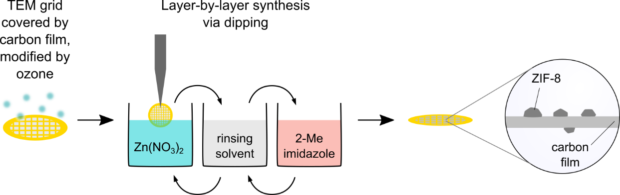
Figure 1. Scheme of ZIF-8 growth with functionalization of an amorphous carbon-covered TEM grid, layer-by-layer growth of ZIF-8 on the grid via dipping, and resulting deposit on the support film.
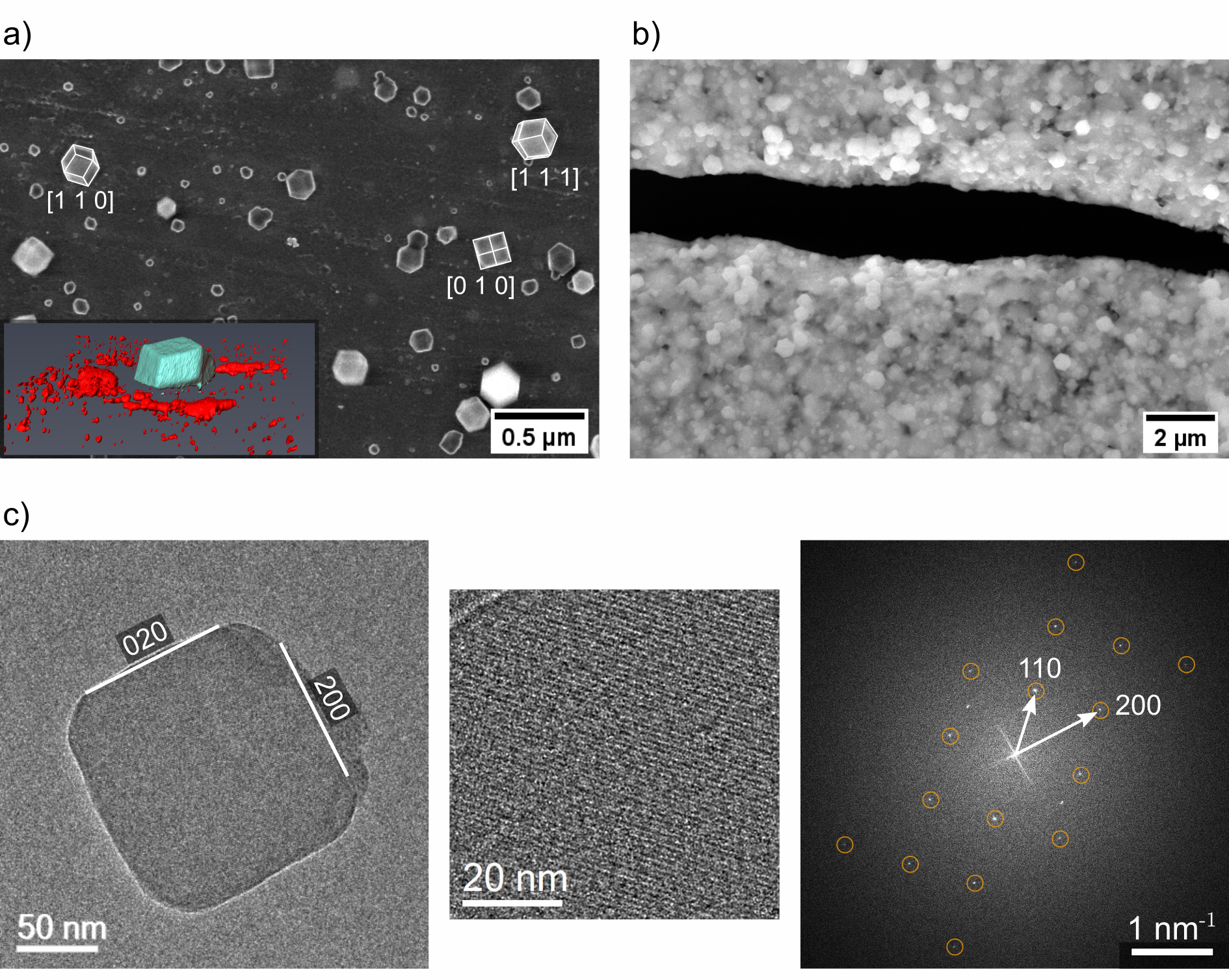
Figure 2. a) 5 keV secondary-electron (SE) SEM micrograph of ZIF-8 obtained from layer-by-layer growth after 50 deposition cycles with low-index projections of rhombic dodecahedral particles [7, 8]. Inset: Surface representation of a tomogram of a ZIF-8 particle (blue) with a planar interface on the support film (indicated by red structures). b) 10 keV SE-SEM micrograph of ZIF-8 after 100 deposition cycles. The film is ruptured in the black region. c) (left) HRTEM image of a ZIF-8 crystallite on aC film after 39 deposition cycles, (center) magnified image section after average-background subtraction filtering. (right) Fourier-transformed image showing reflections that are compatible with the ZIF-8 [001] zone axis [9].
References
[1] Kaskel, The Chemistry of Metal-Organic Frameworks, Wiley-VCH Verlag GmbH & Co. KGaA, Weinheim, Germany (2016)
[2] Heinke and Wöll, Adv. Mater. 31, 1806324 (2019)
[3] Moghadam et al., Chem. Mater. 29, 2618 (2017)
[4] Shekhah and Eddaoudi, Chem. Commun. 49, 10079 (2013)
[5] Park et al., P. Natl. Acad. Sci. USA 103, 10186 (2006)
[6] Zhu et al., Nat. mater. 16, 532 (2017)
[7] Cravillon et al., CrystEngComm 14, 492 (2012)
[8] Hugenschmidt et al., Part. Part. Syst. Charact. 37, 2000209 (2020)
[9] Park et al., CCDC 602542: Experimental Crystal Structure Determination (2006)
[10] We acknowledge funding by the Deutsche Forschungsgemeinschaft (DFG, German Research Foundation) under Germany’s Excellence Strategy – 2082/1 – 390761711 and thank the Carl Zeiss Foundation for financial support.